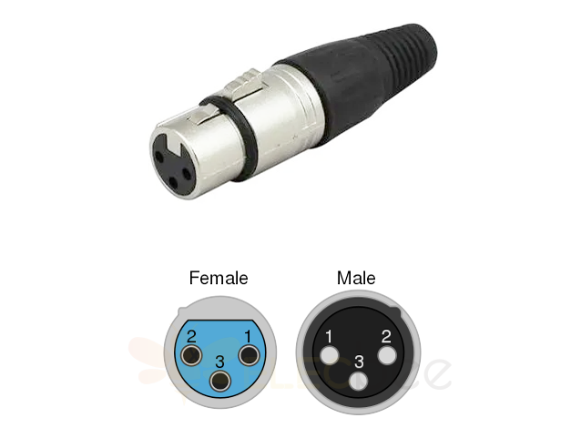
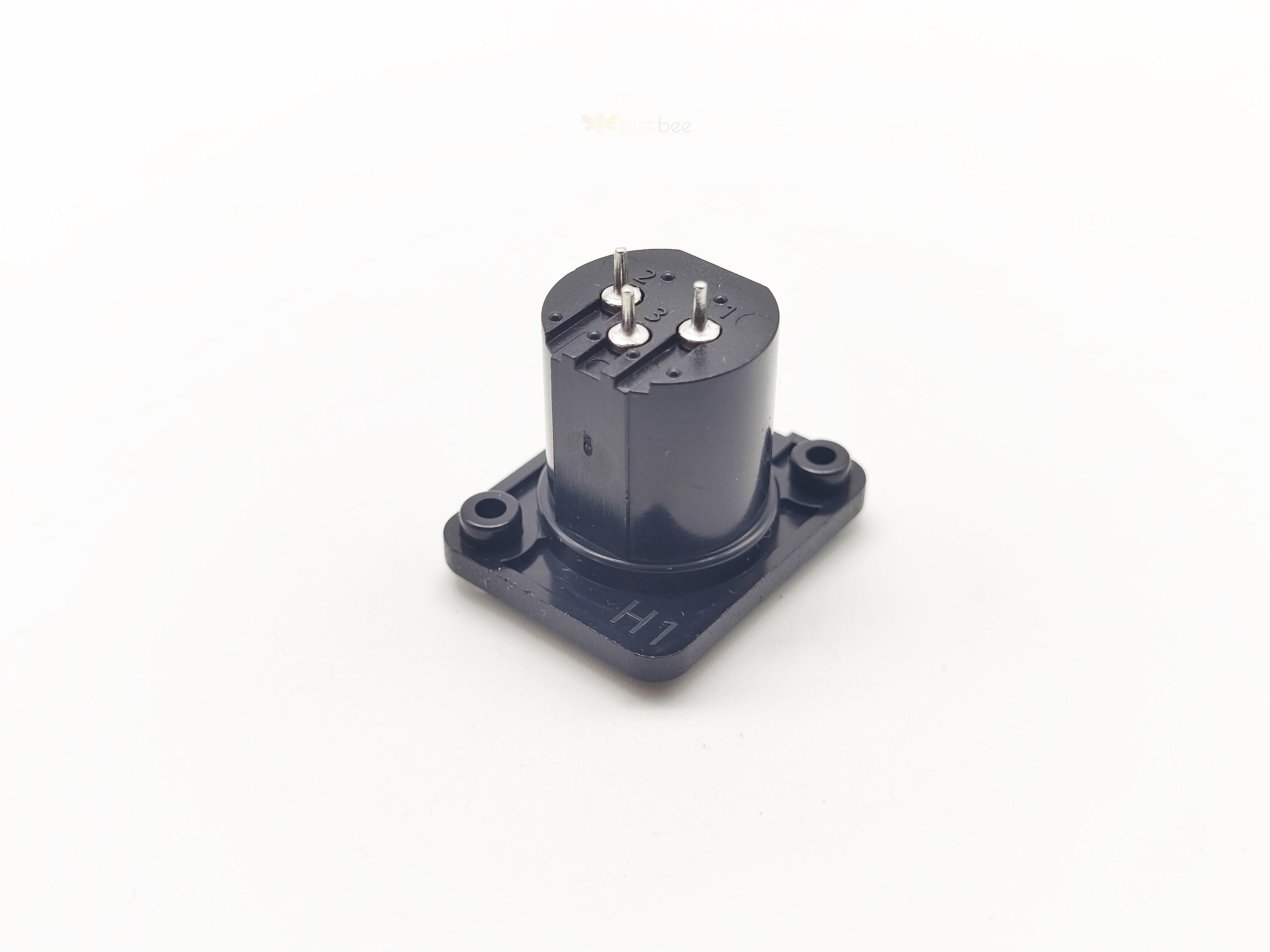
The XLR connector, commonly known as the Cannon connector, was originally a "Cannon X" series of terminals, later versions included Latch as the "Cannon XL" series, and then a Rubber covering on the terminal contact surface, which is the source of the acronym XLR.
The XLR terminal has basically three more needles, and can have a larger number of needles.
Interface introduction

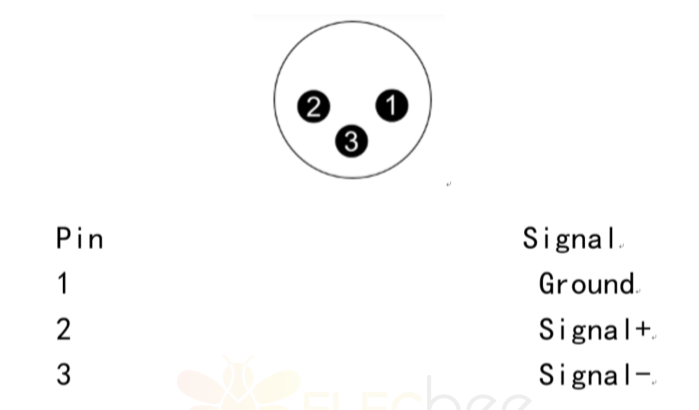
The Cannon connector, commonly known as the Cannon connector, is a completely different Analog Audio cable from the RCA(lotus head interface). The Balanced Analog Audio interface uses two channels to deliver the same signal but the opposite phase of the signal. The receiving device subtracts the two sets of signals, and the interference signals are cancelled out, thus obtaining high quality analog signals. The joint is composed of three contacts, respectively 1- Ground grounding; 2-- hot end (+ grade); 3-- cold end (- level), of course, there are some equipment specified 3 is the hot end (+ level); 2 is the cold end (- level), this should read the equipment manual. Cannon heads are commonly used to connect professional audio and video equipment to microphones, and are sometimes used in home and computer microphones.
Pin definition

Advantage
Cannon connectors are the most widely used connectors in professional audio systems. They can be used to transmit all kinds of audio signals in audio systems. Generally, balanced input and output terminals are connected by Cannon connectors. In a sense, the use of cannon connector is also one of the characteristics of professional audio system different from civil audio, its advantages are:
A. Balanced transmission mode, strong anti-interference ability, conducive to long-distance transmission (no more than 100 meters).
b, with spring locking device, reliable connection, not easy to pull off.
c. The signal direction is specified by the connector to prevent errors on the connection.
Cannon plugs are male and female, and receptacles are also male and female. The male contact is the pin, while the female contact is the jack. According to the common international practice, the male plug or socket as the output end of the signal; The female plug and socket are used as the input end of the signal.
3.5 Plug to Canon Jack Sequence
1, audio cable is generally three core, two about the channel, a shield. Connect the 3.5 plug: Screw one of the channel wires to the shield wire, and the other (usually red) to the fire end of 3.5 (i.e. the main port). The twisted end is connected to the ground port of 3.5.
2. Canon: Read each port number. Points 1, 2, 3, the 3.5 fire end of the root first received Canon 2, the other two roots do not screw up, respectively received Canon 1, 3 mouth.
3, if it is a two-core audio cable, 3.5 head respectively connected to the fire end of the audio cable and the ground end, Canon head or fire end 2, and 1, 3 to use the line to short circuit the two ends of the audio line can be welded on the shielding line.
4. Note that because the 3.5 plug is relatively small, it is easy to cause a short circuit between the two wires. It is best to use the wrapping cloth in the middle of the two wires.

Elecbee is a company specializing in the research and development, production and sales of electronic connectors, adapters and antennas. Whether it is technology, research and development, production or business, it is in the leading position in the industry. If you want to know more about our products or need related help and support, you can directly communicate with our technical staff in real time on the website or send an email to service@elecbee.com. All Elecbee staff look forward to cooperating with you.


