1. Support multiple working modes;
2. Support setting the current upper limit;
3. Support setting the current lower limit;
4. Support setting output startup value;
5. Support setting output stop value;
6. Support NC and NO output;
7. High sensitivity;
8. Low power consumption;
9. Support over current control;
10. Digital tube display;
11. High precision;
12. Support power-off memory function;
13. Work output LED indicator.
Specifications:
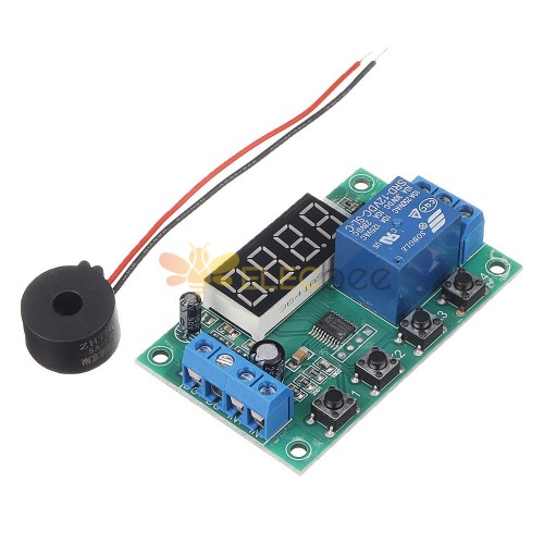
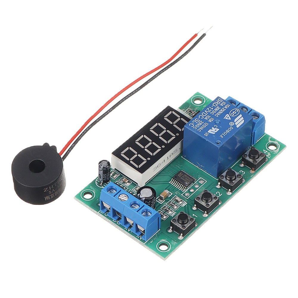
Product Name:AC 220V 5A Current Detection Module
Working Voltage:DC 5V/12V/24V(Optional)
Measured Load Voltage:AC 220V
Measured Load Current:0~5A
Measured Current Accuracy:0.01A
Controlled Load Voltage:AC 250V or DC 30V
Controlled Load Current:10A
Stand-by Current:15mA
Working Temperature range:-40℃~85℃
Working Humidity range:0%-95%RH
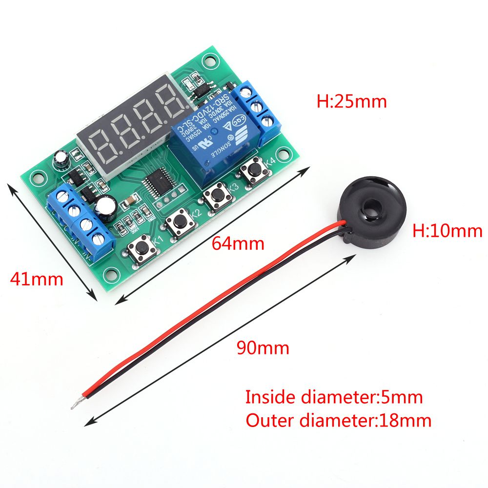
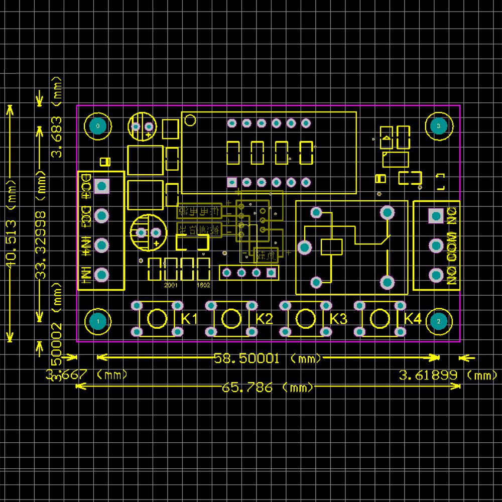
Size: 66x41x25 mm
Button/Screen Description:
1. Display will display current measured current as ‘00.00’ when power on or normal display status.Unit is ampere.
2. Screen will display mode such as ‘P-21’ at set mode.
2.1. ’P’ will flashing at set mode.
2.2. The second bit is ‘-’ which is a separator and user can be ignored and no meaning.
2.3. The third bit like ‘2’ is mode select.It can be 1~5.User can adjust mode by button ‘K2’.
2.4. The fourth bit like ‘1’ is function select.It can be 1~2.User can adjust function by button ‘K3’.
3. K1:Set Mode and set Current Lower/Upper Limit Value.
3.1. User need keep press for more than 1second when press K1 for the first time when enter into set mode.It is used to prevent false triggering;
3.2. At the first press K1.It is menu to set mode and select by button K2 and K3;
3.3. At the second press K1.Screen will flashing and display like ‘00.05’.It is menu to set the current lower limit value L1.It means threshold L1 is 0.05A.Press button K2 to increase threshold L1 and K3 to decrease threshold L1.
3.4. At the third press K1.Screen will flashing and display like ‘00.10’.It is menu to set the current upper limit value L2.It means threshold L2 is 0.10A.Press button K2 to increase threshold L2 and K3 to decrease threshold L2.
3.5. At the fourth press K1.It will return to normal display current measured current.Indicates that it is in standby mode.
4. K2:Set mode and increase threshold value.
5. K3:Set mode and error calibration.
5.1. Set mode and increase threshold value at Set Mode.
5.2. Press button K3 in standby mode.It is used to zero adjustment and error calibration.
6. K4:Reserved button.
7. Set parameters will save in standby mode if power off.
Function:
1>.L1:The current lower limit.
2>.L2:The current upper limit.
3>.L1
4>.Relay default OFF.
5>.P-11:Relay ON when the Measured Current is higher than L1;Relay OFF when the Measured Current is lower than L1 again.
6>.P-12:Relay ON when the Measured Current is higher than L1;Relay will keep ON no matter what the Measured Current is after relay turn on.Relay OFF if re-start power supply.
7>.P-21:Relay ON when the Measured Current is higher than L2;Relay OFF when the Measured Current is lower than L1.
8>.P-22:Relay ON when the Measured Current is higher than L2;Relay will keep ON no matter what the Measured Current is after relay turn on.Relay OFF if re-start power supply.
9>.P-31:Relay ON when the Measured Current is lower than L1;Relay OFF when the Measured Current is higher than L2.
10>.P-32:Relay ON when the Measured Current is lower than L1;Relay will keep ON no matter what the Measured Current is after relay turn on.Relay OFF if re-start power supply.
11>.P-41:Relay ON when the Measured Current is between L1 and L2;Otherwise relay OFF.
12>.P-42:Relay ON when the Measured Current is between L1 and L2;Relay will keep ON no matter what the Measured Current is after relay turn on.Relay OFF if re-start power supply.
13>.P-51:Relay ON when the Measured Current is lower than L1 or higher than L2;Otherwise relay OFF.
14>.P-52:Relay ON when the Measured Current is lower than L1 or higher than L2;Relay will keep ON no matter what the Measured Current is after relay turn on.Relay OFF if re-start power supply.Using Steps:
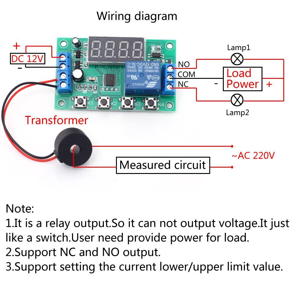
1. Connect Current Transformer Sensor at ‘IN+’ and ‘IN-’.
2. Connect power supply DC 12V at ‘DC+’ and ‘DC-’(Please don’t connect load before set work mode).
3. Make sure what work mode require.
4. Keep press button K1 for more than 1second enter into set work mode as listing in ‘Function’.Press K2 and K3 to select mode.
5. Press button K1 at the second time to set the current lower limit value L1.Press K2 and K3 to change value.
6. Press button K1 at the third time to set the current upper limit value L2.Press K2 and K3 to change value.
7. Press button K1 at the fourth time to return to normal display current measured current.
8. Press button K3 to error calibration.
9. Test the set parameters based on the output indicator and the sound from the relay.
10. Cut off the power supply and then connect load at output.Note:The load needs to be powered separately.Module can not output voltage.
11. Turn ON power for module and use module.
Note:
1. Its work voltage is DC 12V and not AC 220V.AC 220V is voltage for the Measured Current.
2. It’s a relay output.So it can not output voltage.It just like a switch.
3. User need provide power supply for load.
4. Wire cannot be reversed.Otherwise the module will be damaged.
Application:
1.Current check
2.Home security
3.Electrical inspection
4.Intelligent circuit control
5.Circuit detection

