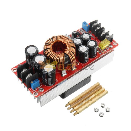
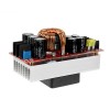
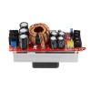
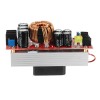
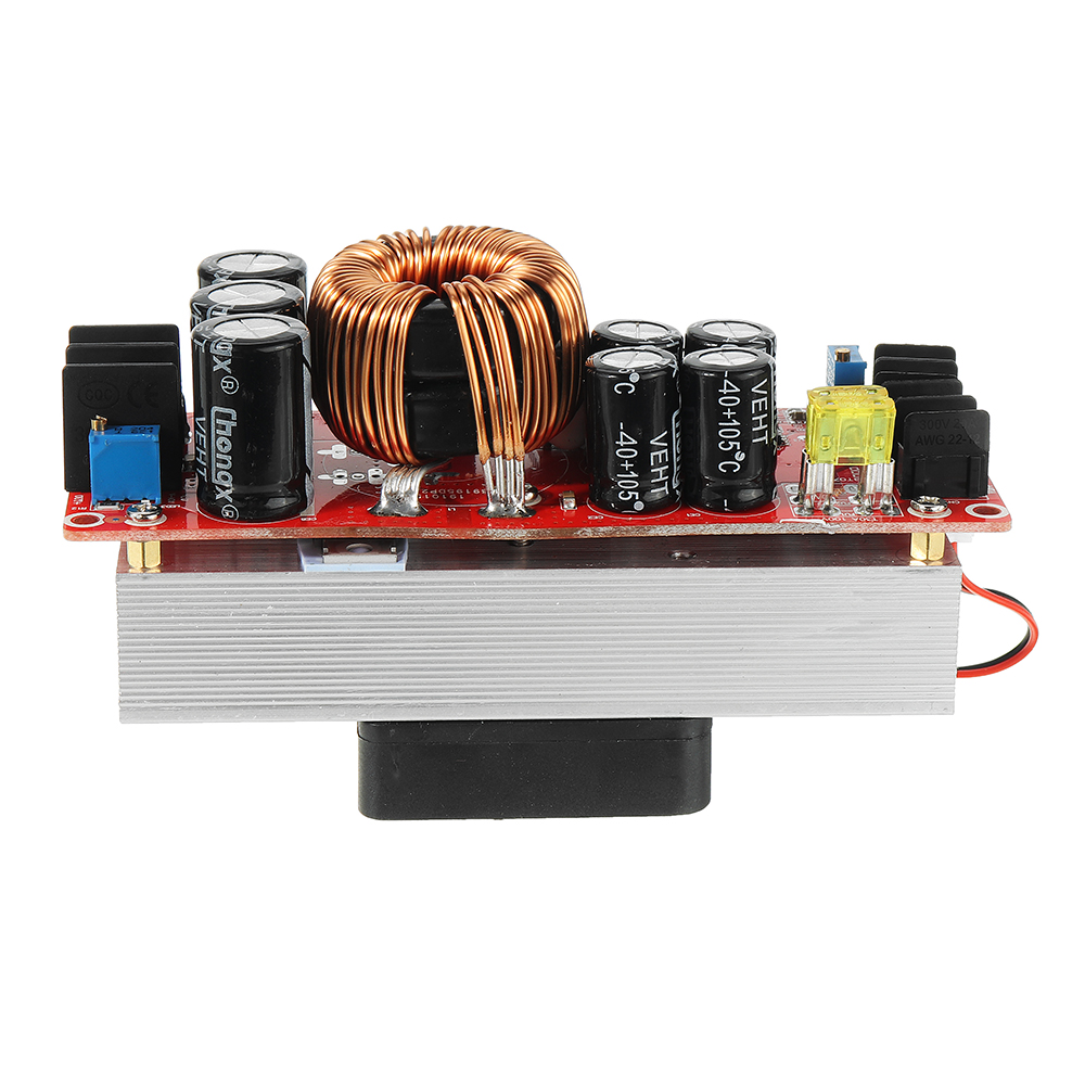
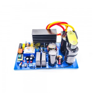
Descriptions:Module model: SZ-BT07CCCV-D1
Module name: 1500W boost constant current module
Module nature: non-isolated boost module (BOOST)
Input voltage: DC10-60V
Input current: 10-30V input voltage, maximum current 30A
31-60V input voltage, maximum current 25A
Static working current: 15mA (12V liters 20V, the higher the output voltage, the static current will increase)
Output voltage: 12-90V continuously adjustable (default output is adjusted to 19V)
12-90V fixed output
Output current: 20A MAX More than 15A, please strengthen the heat dissipation (related to the input and output voltage difference, the larger the differential pressure, the smaller the output current)
Constant current range: 0.8-20A (+/-0.3A)
Input anti-reverse connection: Yes (150A power MOS anti-reverse)
Low battery protection: self-recovery (8-50V adjustable)
Working temperature: -40~+85 degrees (enhance heat dissipation when the ambient temperature is too high)
Working frequency: 150KHz
Conversion efficiency: 92%-97% (efficiency is related to input, output voltage, current, differential pressure. Low differential pressure)
Input overcurrent protection: Yes (input over 35A, automatic protection, power does not boost)
Short circuit protection: Yes (input 30A fuse) Double short circuit protection, safer to use.
Input reverse connection protection: Yes (150A power MOS tube anti-reverse. Can be reversed for a long time)
Installation method: 4 3mm copper columns
Wiring method: terminal block (please use high current pure copper wire)
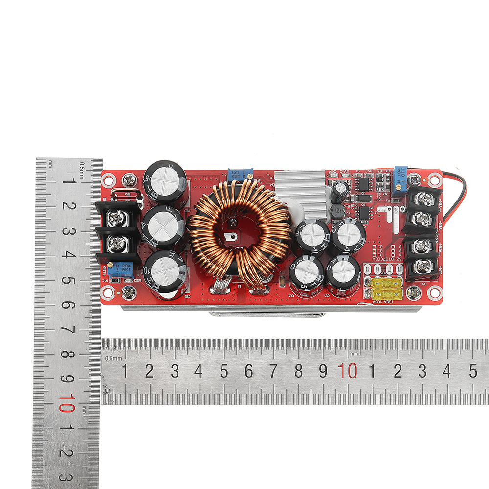
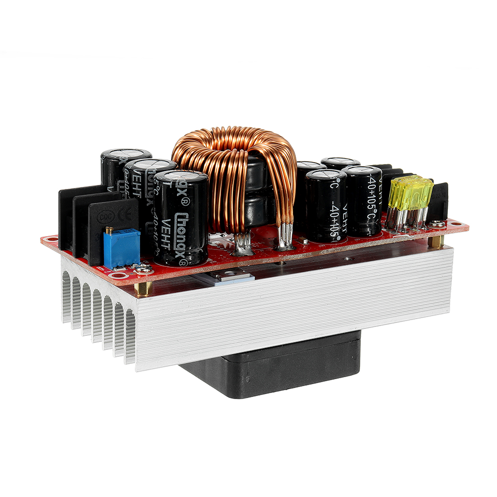
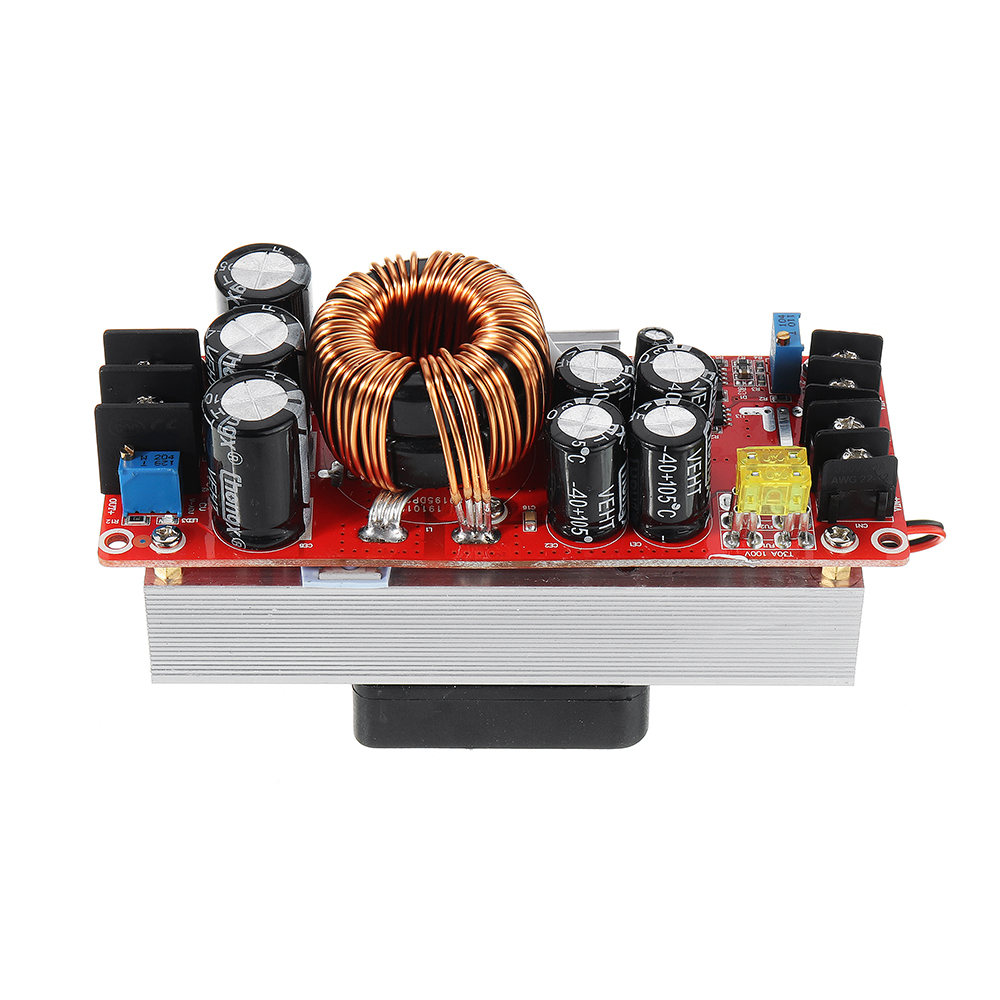
Module size: length 130mm width 52mm height 84mm (high copper column and fan), length 130mm width 52mm height 67mm (high without copper column and fan
Module single weight: 490 grams
Output power: = input voltage * 30A, such as: input 12V * 30A = 360W The maximum power when inputting 12V is 360W
Input voltage *30A For example: input 24V * 30A = 720W, that is: the maximum power is 720W when inputting 24V
When using the boost power supply should pay attention to the following points:
1. the output polarity cannot be reversed or short circuit.
2. when using batteries as the input source, you must lower the battery protection, otherwise it will damage the battery and power supply
3. Input power supply voltage must be above 10V.
4. When the power supply is used for the input power supply, the input power and the output voltage of the input power supply are the first to be unloaded. Then pick up the load. (must ensure that the switching power supply has been working).
5. When the constant current mode is used to set the voltage, the constant voltage must be higher than the input voltage.Do not use the way of short circuit output current,the circuit structure of the boost module can not be adjusted in short circuit way.
6. If the input voltage fluctuation range is lower than the set output voltage,then the output voltage is constant, it is to ensure that input is lower than the output voltage.Power description:
Since the input current is 30A at 10-30V and the input current is 25A at 31-60V, the output power is related to the input voltage. The higher the input voltage, the higher the power (the input voltage * input current is equal to the power of the whole machine). For example, the input 12V*30A power is 360W. The input 24V*30A is 720W. When the input voltage is 36V, the input current is the maximum power of 25A. For 900W.
The main advantage:
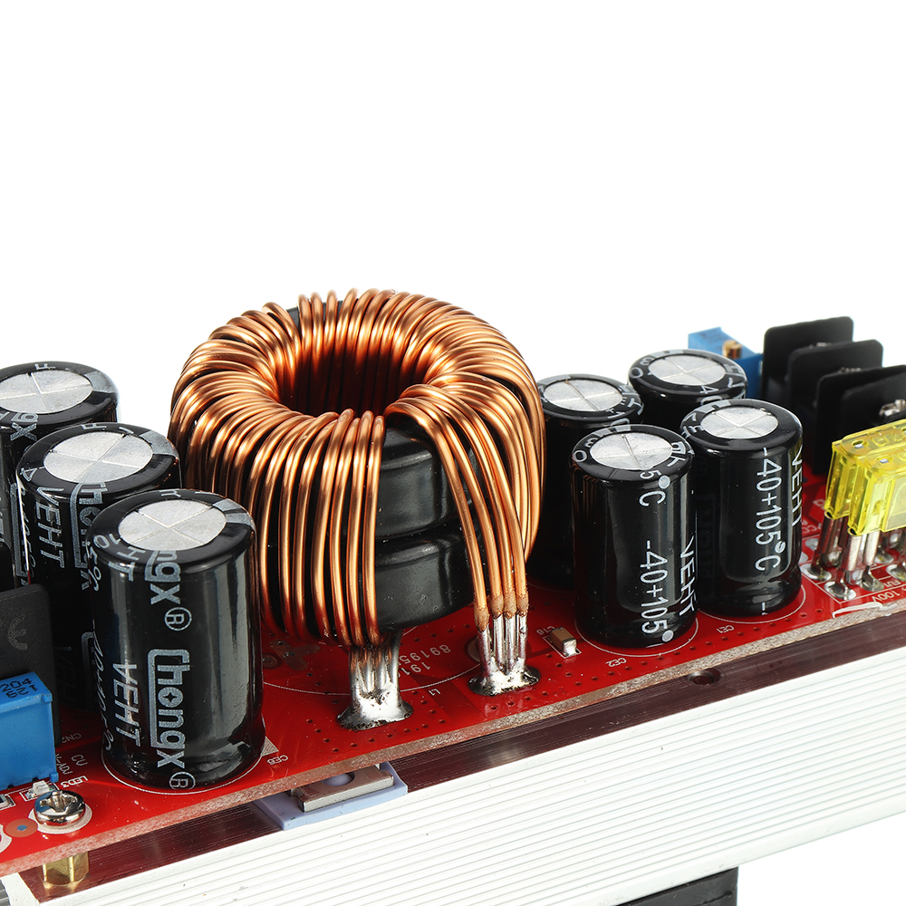
1. The power supply uses double iron silicon aluminum and four 1.2MM pure copper wires and is spared. 100V/210A low resistance power MOS, high power and high current input, suitable for high power LED, motor use
2. There is input MOS anti-reverse protection, do not worry about the input connection and burn the power supply
3. Low battery protection does not damage the power module and battery due to battery over-discharge when input from the battery.
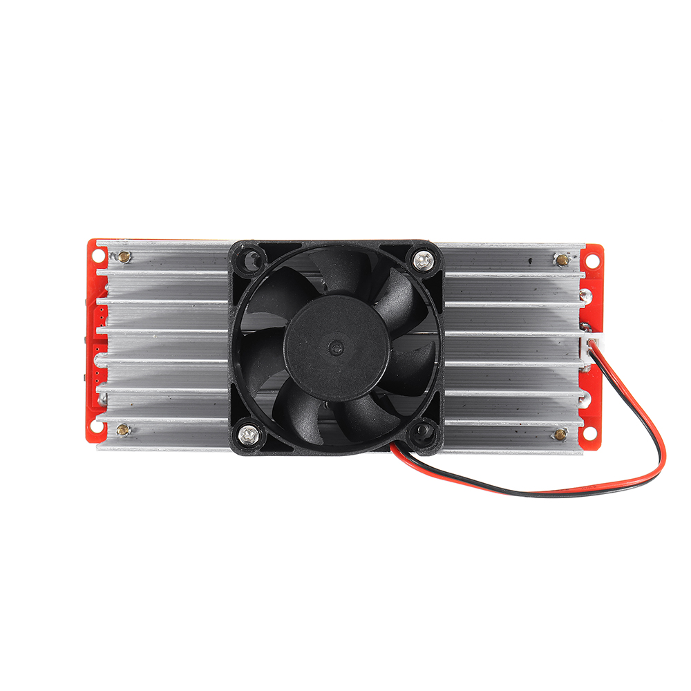
4. Thickened heat sink and intelligent temperature control fan for heat dissipation.
Voltage regulation:
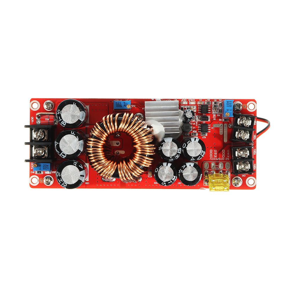
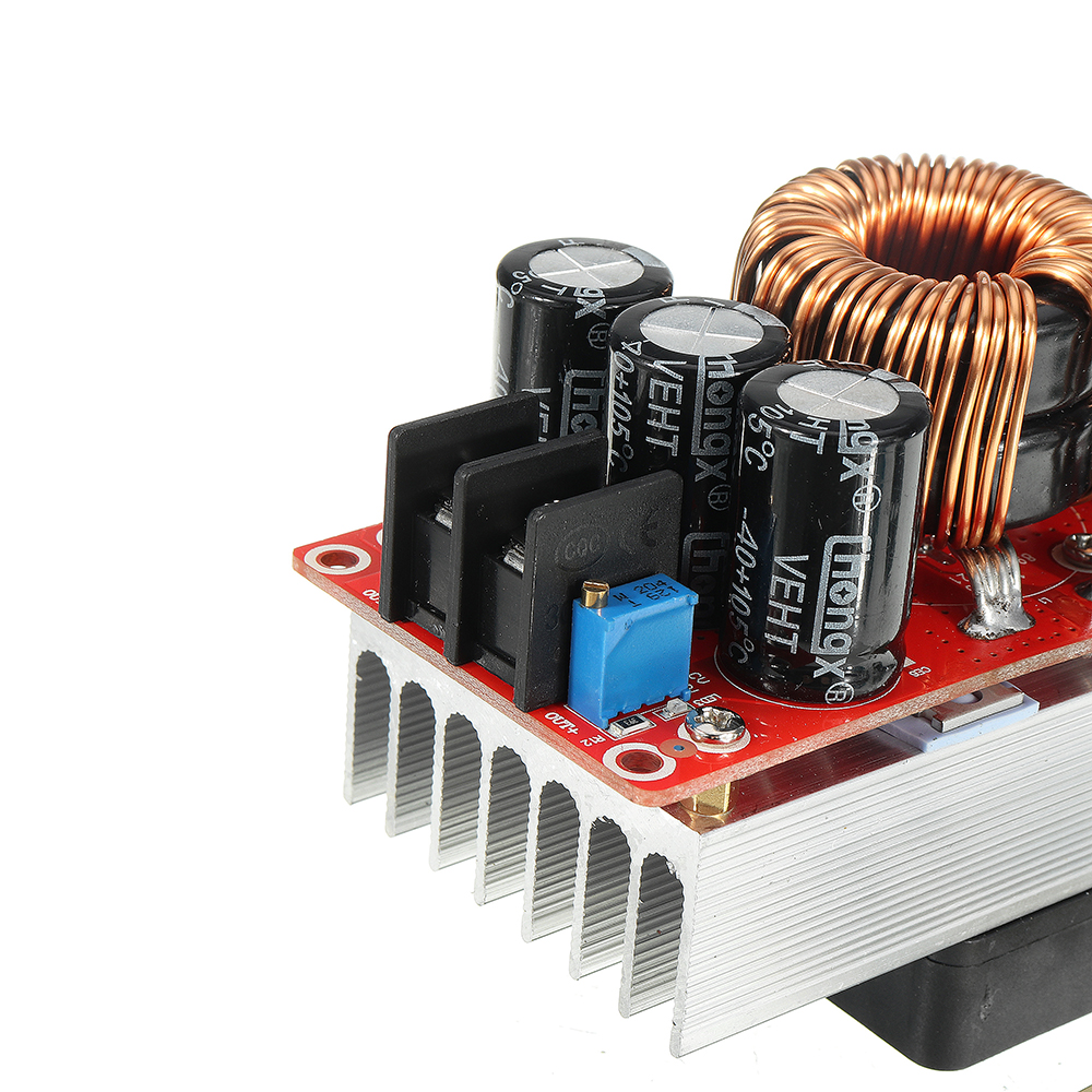
When the power supply is unloaded, use a flat-blade screwdriver to adjust the output terminal "V-ADJ" potentiometer (marked in the figure below) to increase clockwise and counterclockwise to adjust). Because the output capacitor capacity is large, the output voltage is When the high voltage is adjusted to a low voltage, the reaction will be slower. The adjustment of the instrument is smaller. (The default output voltage is adjusted to 19V shipment. If you need to adjust other voltage values, please explain or leave a message)
Current regulation:
Adjust the "CC A-ADJ" potentiometer counterclockwise for about 30 turns, set the output current to the minimum, connect the load such as the LED battery, and adjust the "CC A-ADJ" potentiometer clockwise to the current you need. For battery charging, after the battery is discharged, it is connected to the output, and adjust the CC A-ADJ to the current you need. When charging, be sure to use the discharged battery to adjust the battery. The more the charge, the smaller the charge current. The default output ESC is shipped to 3A. If we need to adjust the current value of the instructions or message. Do not use the short-circuit output to adjust the current, the circuit structure of the boost module can not be adjusted by short circuit,
Enter low battery protection adjustment:
Low battery protection mainly prevents over-discharge of the battery when the input power is the battery. The battery voltage is too low to damage the power module and the battery. The input is also the low-voltage protection when switching the power supply.
Method 1: For example, set 12V battery low battery protection. Connect a 10V voltage to the input terminal of the power module. Use a flat-blade screwdriver to adjust RV1 (clockwise protection voltage value is increased, counterclockwise protection voltage is turned down) until the UVLO lamp is on. At this time, the low battery protection voltage is 10V. When the voltage drops to 10V, the power module does not rise (the input voltage is equal to the output voltage). Only after the input voltage is higher than 10V, the power supply starts to resume boosting.
Method 2: Input the battery or switch power supply. If the UVLO lamp on the board is off, adjust the RV1 potentiometer counterclockwise to brighten the UVLO lamp, then turn it clockwise two turns. If the UVLO lamp is on, turn the RV1 potentiometer clockwise, turn off the UVLO lamp, and then turn it two turns. (Adapt to 8V-45V voltage)
1 x 1500W boost constant current module

