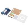
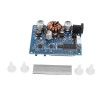
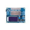
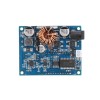
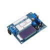
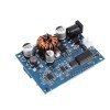
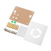
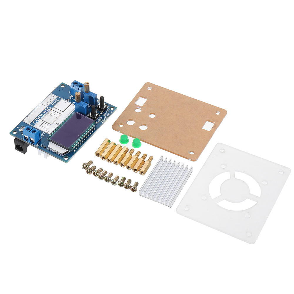
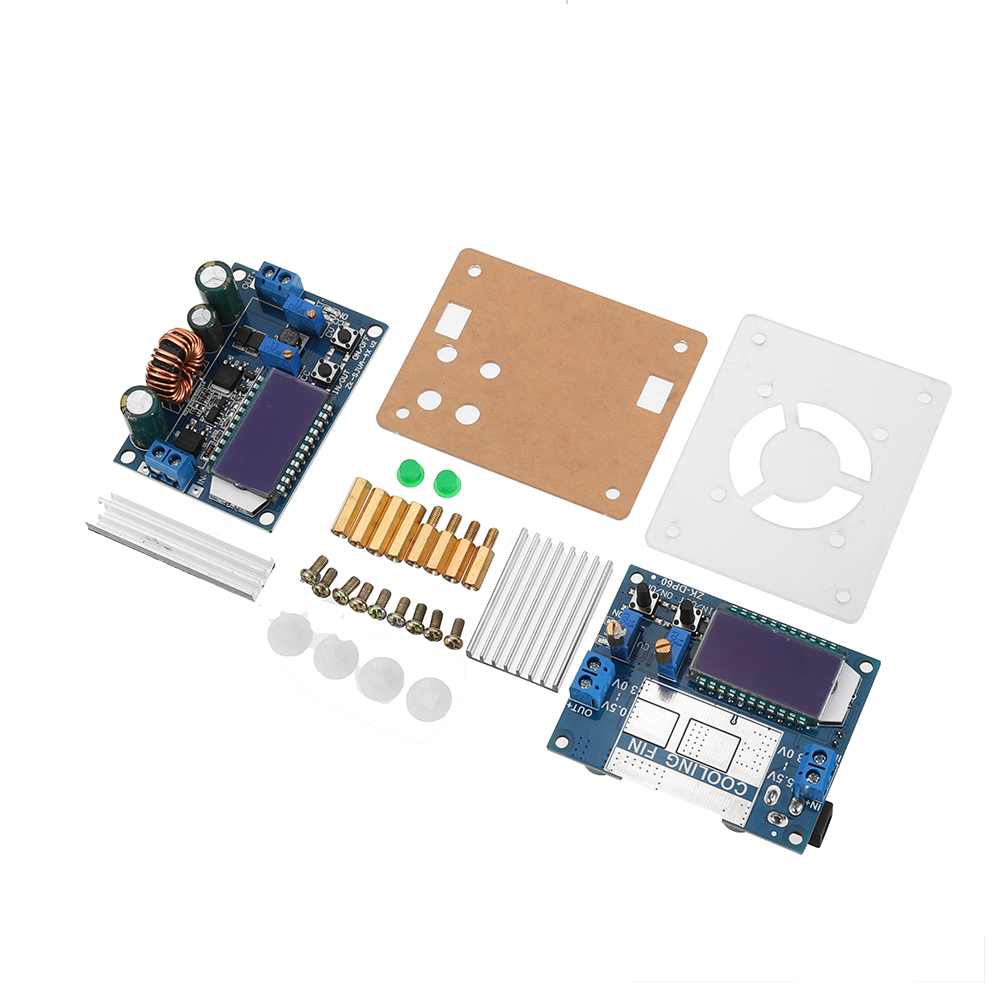
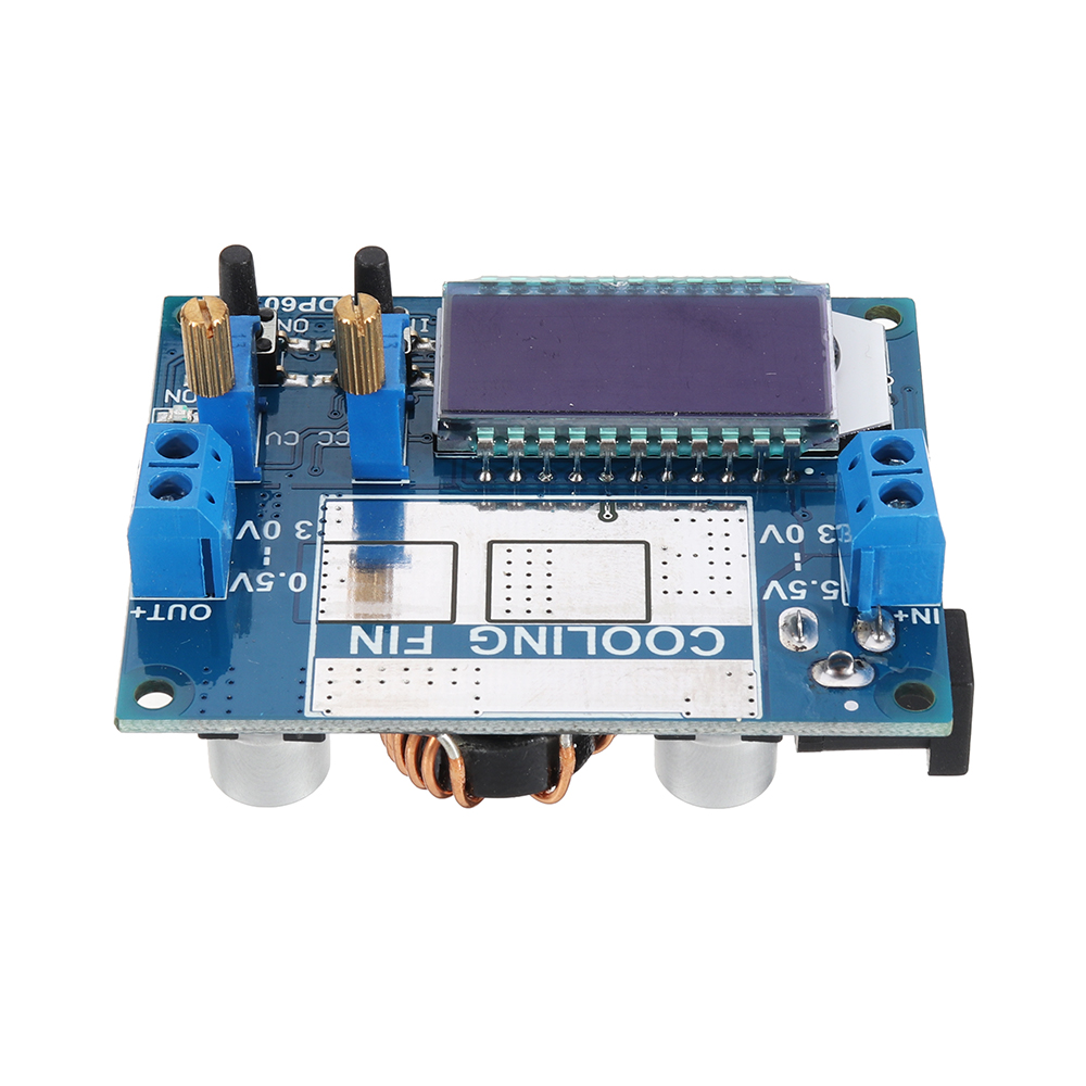
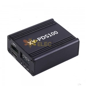
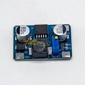
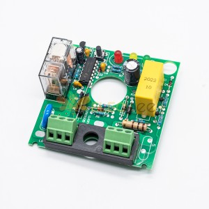
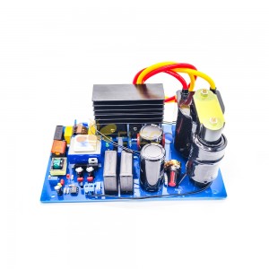
- LCD can display input and output voltage, output current output power;
- Input anti-reverse protection, reverse connection will not burn;
- It can be boosted, can be stepped down, the output voltage can be adjusted freely from 0.5-30V, and the current limit of 0-4A can be adjusted freely;
- The output is protected against backflow, and there is no need to add an anti-backflow diode when charging the battery;
- The button controls the output ON/OFF status, and the power-on default can be set to ON or OFF;
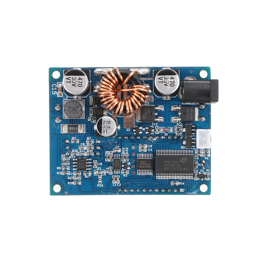
- Using the buck-boost chip as the main controller, the external 60V 75A MOS tube is used as the switch tube, - double 60V 5A SS56 Schottky for rectification, 60V withstand voltage value, better than the market XL6009/LM2577 immature solution (many The device withstand voltage is insufficient, the MOS tube and Schottky diode withstand voltage must be greater than the input plus input voltage value);
- The output ripple is small and there is LC filtering;
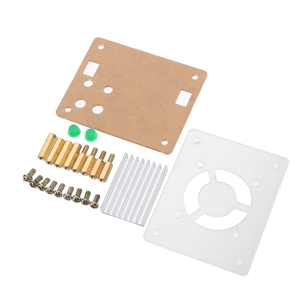
- With heat sink, the module supports the spacer.
Specifacations:
Input voltage: 5.5-30V (when the input voltage is 5V, the buck-boost can also be realized, but the voltage and current measurement is not accurate; below 4.7V, under-voltage protection)
Output voltage: 0.5-30V
Output current: can work stably at 3A for a long time, and can reach 4A under enhanced heat dissipation
Output power: natural heat dissipation 35W, enhanced heat dissipation 50W
Voltage display resolution: 0.05V
Current display resolution: 0.005A
Conversion efficiency: about 88%
Soft start: Yes (very large power load module may fail when started)
Input reverse connection protection: Yes
Output end anti-backflow: Yes
Short circuit protection: Yes
Working frequency: 180KHz
Size: 66*48*21mm
Mounting hole: diameter 4mm
Instructions:
1. Use as a common buck-boost module with overcurrent protection
(1) Adjust the CV constant voltage device so that the output voltage reaches the voltage you want.
(2) Use the multimeter 10A current file to measure the output short-circuit current (directly connect the two test leads to the output terminal), and adjust the CC constant current potentiometer to make the output current reach the predetermined overcurrent protection value. (For example, if the current value displayed by the multimeter is 2A, then the maximum current can only be 2A when you use the module, and the red constant voltage constant current indicator will be on when the current reaches 2A, otherwise the indicator will be off)
Note: When using in this state, there will be a voltage drop of 0~0.2V after the load is connected, and there will be a certain voltage drop on the input and output wires when the current is high. This is normal!
2. Use as a battery charger
Modules without constant current function cannot be used to charge the battery. Because the voltage difference between the battery and the charger that consumes electricity is too large, the charging current is too large, causing damage to the battery. Therefore, the battery should be used at the beginning. Stream charging, when the charging reaches a certain level, it automatically switches back to constant voltage charging.
(1) Determine the float voltage and charge current of the rechargeable battery you need; (If the lithium battery parameter is 3.7V/2200mAh, then the float voltage is 4.2V and the maximum charge current is 1C, ie 2200mA)
(2) Under no-load conditions, the multimeter measures the output voltage, and adjusts the constant voltage positioner to make the output voltage reach the float voltage; (If charging the 3.7V lithium battery, adjust the output voltage to 4.2V)
(3) Use the multimeter 10A current file to measure the output short-circuit current (directly connect the two test leads to the output terminal), and adjust the constant current potentiometer to make the output current reach the predetermined charging current value;
(4) Connect the battery and charge it.
(Steps 1, 2, and 3 are: input terminal is connected to the power supply, and the output terminal is not connected to the battery.)
3. As a high power LED constant current drive module
(1) Determine the operating current and maximum operating voltage at which you need to drive the LEDs;
(2) Under no-load conditions, the multimeter measures the output voltage, and adjusts the constant voltage positioner to make the output voltage reach the maximum working voltage of the LED;
(3) Measure the output short-circuit current with the multimeter 10A current file, and adjust the constant current potentiometer to make the output current reach the predetermined LED operating current;
(4) Connect the LED and test the machine.
(Steps 1, 2, and 3 are: input is connected to the power supply, and the output is not connected to the LED.)
Note: When using this module over 3A, 35W, please strengthen the heat! ! !
Precautions:
1. Module input IN-disable and output OUT- short circuit, otherwise the constant current function will be invalid.
2. Please ensure that the power of the power supply is greater than the power required by the output load!
3. If the module wants full load output, the input voltage should be 8V or more. When the input voltage is 5V, the output power is about 15W, and the voltage ammeter fails. The module current value is up to 4A, subject to the maximum output power, such as output 17V, the current should be no more than 2A.
4. The module has output short-circuit protection. After short-circuit protection, the module automatically turns off the output, and the module can be restored after power-on. If your power supply has no output current-limit protection, it is recommended to connect the fuses in the front end of the module to improve the safety factor.
5. The module has input undervoltage protection function. The default is about 4.7V. After this value is lower, the output will be automatically disconnected and the module can be restored after power-on (note that the voltage at the module port is larger when the input current is larger. Do not ignore the partial pressure on the input wire).


