1. One key measurement operation, auto power off delay. Shutdown current is only 20nA, support for battery operation.
2. Automatic detection PNP and NPN bipolar transistor, N, P-channel MOSFET, JFET FET, diodes, two diodes, thyristors, resistors, capacitors, inductors. Automatic detection pin definitions.
3. Measuring the current amplification factor (B) of the bipolar transistor and the turn-on voltage of the emitter junction (Uf). Darlington transistor amplification factor can be identified by the high threshold voltage and high current.
4. Can detect bipolar transistors and MOSFET's internal protection diodes and displayed on the screen.
5. Measuring the threshold voltage and the gate capacitance of the MOSFET.
6. Support two resistance measurements, the potential can be measured. If the potentiometer is adjusted to its end, the tester can not distinguish between the middle and the ends of the pin.
7. Resistance measurement resolution is 0.1 ohms, the maximum value of 50M ohms measurements.
8. Capacitance measurement range from 25pf to 100mF (100000 UF). Resolution up to 1 pF, inductance measurement range 0.01MH-20H, otherwise it will appear as a resistor, inductor DC resistance is higher than if Europe 2100 will also be displayed as a resistor.
9. It can detect 2UF above capacitor equivalent series resistance (ESR), a resolution of 0.01 ohms. This feature is very important for the detection of the capacitor performance.
10. It can display symbols of the two diodes in the right direction, also shows the forward voltage drop.
11. LED detection for diode forward voltage drop higher than normal. Dual LEDs detected as double diode. Simultaneous detection of light-emitting diodes will flash.
12. Time for each test is about two seconds, only the large capacitance and inductance measurements will take a long time.
Note:
Short three test side, into the test, the screen prompts correction step. When prompted to disconnect the short end of the calibration time off three tests will continue, when prompted in the 1-3 foot access 100nF capacitor over time, access to distribution after correction capacitors 1uF program will automatically enter the next step. Correction until the end of the restart to complete the correction.
Specifications:
Material: PCB
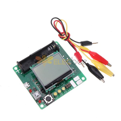
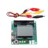
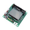
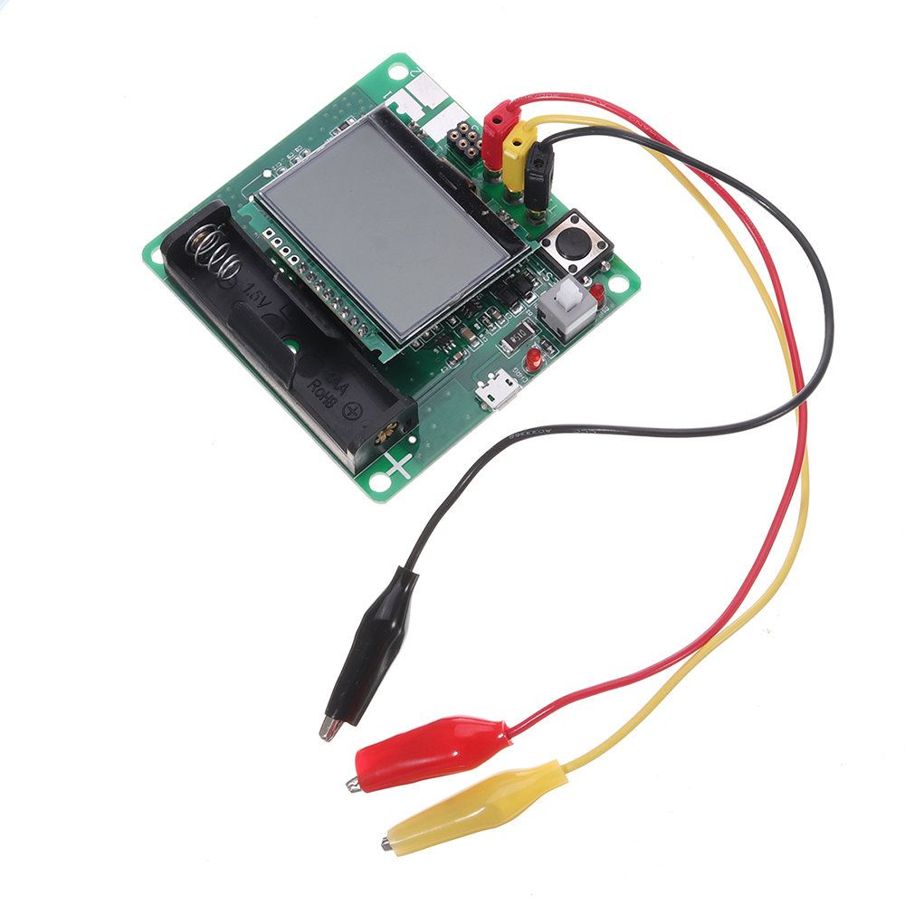
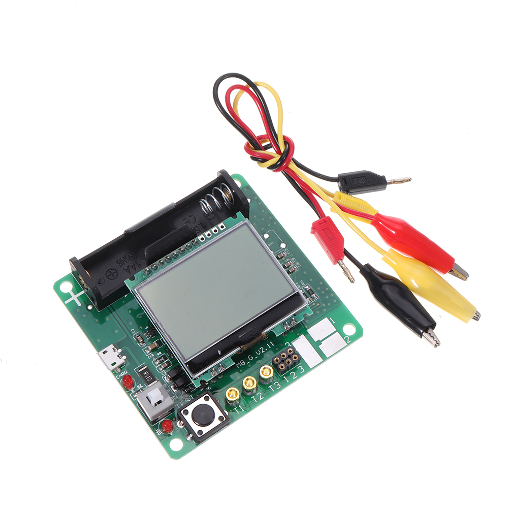
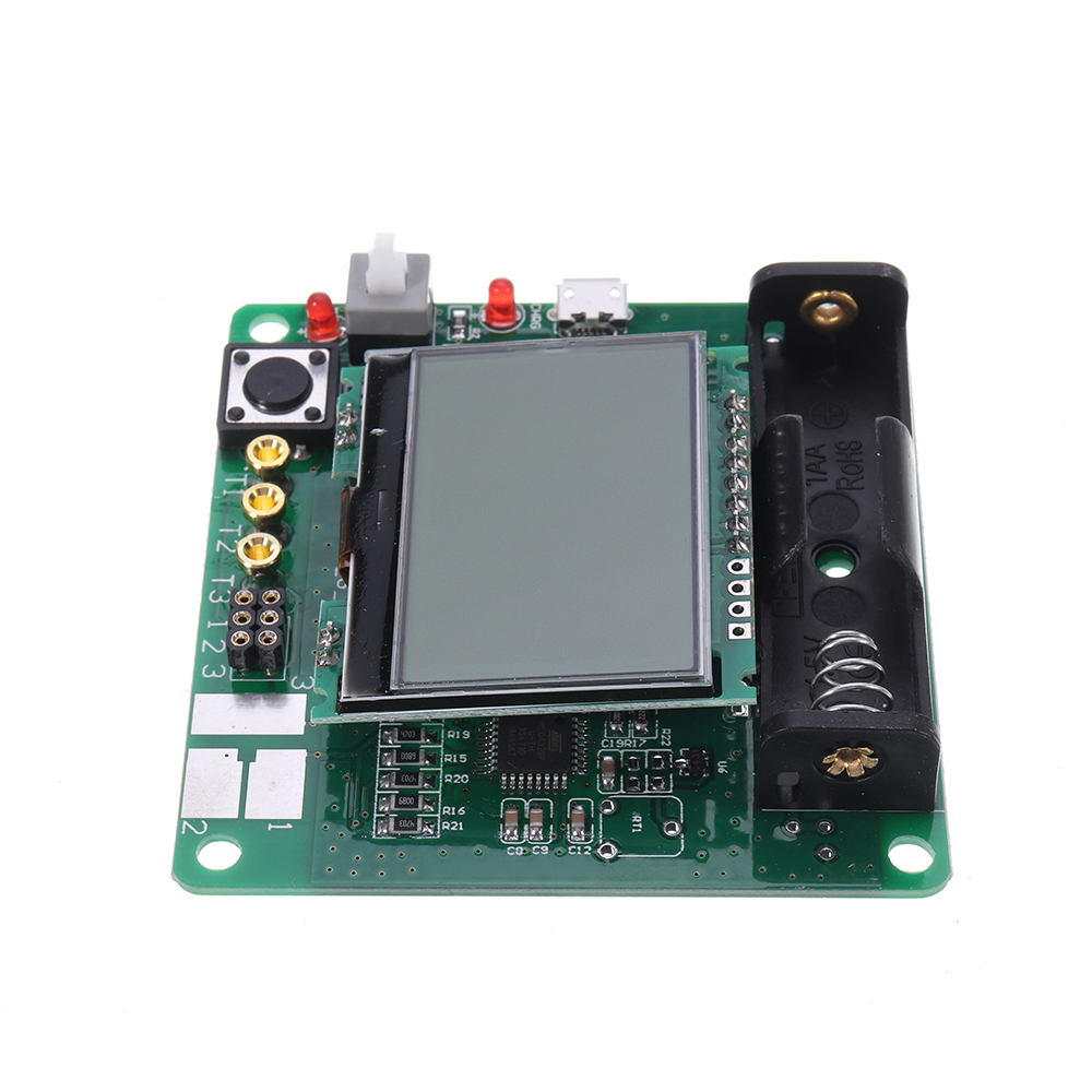
Display: 12864 LCD display
Battery: 3.7V lithium battery Model: 14500 (not included)
Size: 7.3 x 7.1 x 1.5 cm
The Main Parameters and Use:
1. using ATmega8, ATmega168 or ATmega328 microcontroller.
2. 2x16 character LCD display results.
3. one-button operation, automatic power off.
4. shutdown current of only 20nA, support for battery operation.
5. low-cost version without the crystal, auto power off. 1.05k version of the software ATmega168 or ATmega328 in sleep mode when no measurement to reduce power consumption.
6. Automatic detection PNP and NPN bipolar transistor, N, P-channel MOSFET, JFET, diodes, dual diode, thyristor SCR.
7. automatically detects the pin layout.
8. the threshold voltage and current amplification factor of the emitter junction of the bipolar transistor measurements.
9. Darlington transistor through a high threshold voltage and high-current amplification factor identified.
10. pairs of bipolar transistors, MOSFET protection diode testing the threshold voltage value and the gate capacitance of a MOSFET is measured.
12. Supports two resistance measurements and symbols show the highest four numbers and units. Both ends of the resistor symbol is shown connected to the tester probes number (1-3). Therefore, the potential can also be measured. If the potentiometer is adjusted to its end, the tester can not distinguish between the middle and the ends of the pin.
13. resistance measurement resolution is 0.1 ohms, the highest measured value 50M ohms.
14. can be detected and measured a capacitor. Maximum four numbers and units. Values can be from 25pf (8MHz clock, 50pF @ 1MHz clock) to 100mF. Resolution up to 1 pF (@ 8MHz clock).
15. may be larger than the value for 2UF capacitor equivalent series resistance (ESR) measured capacitance value. Resolution of 0.01 ohms and a two-digit numeric display. This feature requires at least 16K Flash ATMEGA (ATmega168 or ATmega328).
16. can display symbols of the two diodes in the right direction. In addition, the forward voltage drop displayed.
17. LED detection for diode forward voltage drop is much higher than normal. Dual LEDs detected as double diode.
18. Zener diode 18 can be detected, if the reverse breakdown voltage is less than 4.5V. This will appear as two diodes, can only be determined by the voltage. Probe around the diode symbol is the same, in which case, you can 700mV threshold voltage close to the true recognition diode anode!
19. If more than three diode type parts inspection, failure to establish the number of diodes another message. This will only happen if the diode is connected to all three probes and at least one diode. In this case, you should only connect the two probes and start measuring again, one by one.
20. measures a single diode reverse capacitance values. Bipolar transistors also can measure, if you connect the base and collector or emitter.
21. need to find a measurement of the full-bridge connection.
22. 25pf capacitor values lower than are usually undetectable, but with a diode in parallel or at least 25pf capacitor in parallel. In this case, you have to subtract part shunt capacitance values.
23. ohm resistor will measure inductance of less than 2100, if you have at least 16K ATMEGA flash. Range from 0: 01mH than 20H, but the accuracy is not good. Measurement results show only a single connection element.
24. test time is about two seconds, only the capacitance and inductance measurements will take longer.
25.software can be set to automatically turn off the power to measure the number of times before.
26.built-in self-test function with selectable clock frequency of 50Hz signal check the accuracy and wait for the call (ATmega168 and ATmega328).
27.optional resistance and zero offset calibration of measuring equipment self-test capability of the port output (ATmega168 and ATmega328). Need a 100nF to 20uF capacitor connected to compensate the analog comparator between pins 1 and 3 of the offset voltage. This can reduce the measurement error 40uF above capacitor. With the same internal calibration capacitor voltage reference voltage is found to internal adjustment reference measurement ADC gain.
If the test current exceeds the holding current, the thyristor and triac can be detected. But some current higher than the semiconductor SCR and triac tester can provide the trigger current. Available test current is only about 6mA! Note that all functions have only used single-chip program memory as more ATmega168.






0-300x300.jpg)
