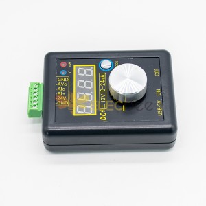
JTGP-1033 Simple Spectrum (with Trace Generator), Simple Signal Source Version V2.0
Attribute: RF Frequency Domain Analysis Tool
Interface: USB
Power supply: USB
Standby current: ≤100mA
Sweep current: & le; 350mA
Sweep bandwidth: 33mHz---4400mHz
Open Tracking Source Output Bandwidth 33 MHz - 3000MHz
Sweep step: ≥33-68.75 mHz/125 Hz, 68.75-137.5 mHz/250 Hz, 137.5-275 mHz/500 Hz, 275-550 mHz/1 kHz, 550~1100mHz/2kHz, 1100~2200mHz/4kHz, 2200~4400mHz/8kHz
Sweep frequency: ≥800spot/second
Sweep Dynamic Logarithmic Ratio: > 50dB
Input detection: 10dBm
Computer side software: NWT4.11.09Edition
Computer operating system: WinXP,win732,win764 (Some of the installations of Win10 can be used and some can't. The reason has not been found yet. It's amazing.)
Purpose: RF circuit Two-port network Frequency and amplitude characteristics analysis is the basis of R&D, debugging and maintenance of RF circuits. The spectrometer is commonly known as a radiofrequency multimeter.
Applicable: Radio enthusiasts, studentsNote:
Because there are two high-frequency oscillators (tracking source oscillator and spectrum local oscillator) on the circuit board of this product, it is unavoidable that they interfere with each other when they work at the same time (especially because the microwave band of the board size 99x75 is over 1500mhz has begun to appear). Simple shielding to reduce this interference effect is very small, do not. Close the structure with a metal enclosure (after all, a prop on your mage's path). Of course, it's feasible for you to redesign the available metal shell structure rationally. After all, radio enthusiasts' brain holes and hands-on abilities are unlimited.
Friendship Reminder:
For curious amateurs who like to use their hands and brains, tens of megabytes bandwidth sweeper may be a better choice. It is really important to have a good command of the high frequency characteristics of the basic L and C, and to have an intuitive feeling. It is also the basis of understanding the higher complex applications. At the same time, it is also the key basic instrument for all designers to design and select materials. It is by no means a substitute for the common multimeter to measure inductance and capacitance. Because their high-frequency parameters are sequences, functions for frequencies, curves, and not just a few dry numbers.
Core Components:
STM32F103: single-chip computer, as a result of the built-in can 2.0 controller has become the most familiar single-chip computer for hardware engineers. At the bottom of the hardware, it is written in the official standard language of “ hardware country ” C MDK, which is convenient for communication.
Adf4351: the traditional VCO + PLL + 6 series high-speed bistable circuits (except 2 circuits, D trigger). 35-2200 MHz is obtained by frequency division. After shaping, the fundamental wave amplitude does not change much, which is difficult to achieve in full bandwidth for high-frequency DDS. (After the signal is divided into frequencies, it must be a rectangular wave, and the amplitude will change to trigger level)
Often play VCO has this experience that the frequency output varies greatly with the amplitude of the fundamental wave. Direct use of this original oscillator can not be used as a measurement of the source. The output fundamental wave amplitude must be stabilized as ADF4351 does.
IAM81008: mixer chip RF up to 5 GHz mixer chip, mixer below 50 MHz 8-foot 6-foot series capacitor to GND optimization. LO local oscillator input must be greater than - 5 dBm, in addition, the IAM81008 power supply electrode must be strictly stable more than 4.85 v. I use the home-made ps3120 for its power supply.
AD8307: Logarithmic Detector Amplifier, Used for Power Measurement, Key Components.
Ch340g: homemade USB to TTL chip, good driver. Generally, STM32F103 is not driven by USB, which reduces the cost of the interruption system of the single-chip microprocessor, although the performance of this single-chip microprocessor exceeds the USB of its own. Ch340g performance-price ratio is very high.
Working Principle:
Physically, any oscillator will not only produce fundamental waves there will always be overtone (homogeneous harmonics, even harmonics, and inter-wave) to filter overtone directly. Sometimes, it is very difficult to filter overtones directly. After mixing the measured signal with the local oscillator, a lot of combined differential frequencies will be obtained. Among them, the fundamental wave of the local oscillator and the external signal of the local oscillator. The difference frequency is the lowest and the amplitude is the largest. Only this difference frequency is obtained by using the low-pass filter or band-pass filter (RBW), which is sent to the logarithmic amplifier at the later stage to detect the frequency and amplitude of the measured signal. The key point is that the fundamental wave amplitude of the local oscillator does not change much at different frequencies, the overtone is not used, because mixing will be low pass (RBW) filter out.
Similarly, the fundamental frequency difference between the tracking source oscillator and the local oscillator is always 120 khz. We can always observe the amplitude change of the 120 kHz difference frequency. This is the principle of differential frequency scanning.


0-300x300.jpg)
