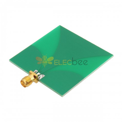
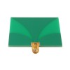
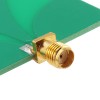
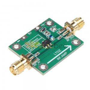
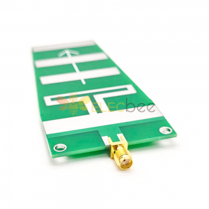
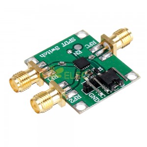
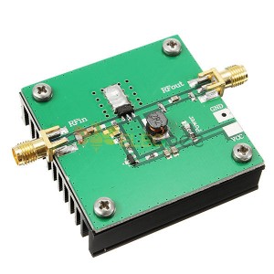
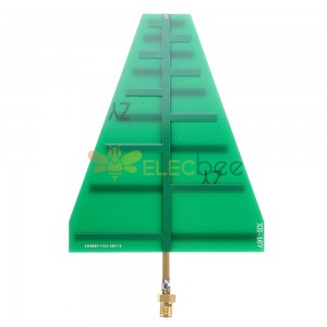
Working frequency: 3-10G
Transmitting power: 5W
Voltage standing wave: less than 2.5
Gain: 2.5
Technical characteristics of UWB:
(1) High transmission rate and large space capacity
For Shannon channel capacity formula, the upper limit of the system's error-free transmission rate in an additive white Gaussian noise (AWGN) channel is:
C=B×log2(1+SNR)
Where B (unit: Hz) is the channel bandwidth and SNR is the signal to noise ratio. In the UWB system, the signal bandwidth B is as high as 500 MHz to 7.5 GHz. Therefore, even if the signal-to-noise ratio SNR is low, the UWB system can achieve a transmission rate of several hundred megahertz to 1 Gb/s over a short distance. For example, if you use a 7 GHz bandwidth, even with a signal-to-noise ratio as low as -10 dB, the theoretical channel capacity can reach 1 Gb/s. Therefore, UWB technology is very suitable for short-distance high-speed transmission applications (such as high-speed WPAN), which can greatly improve the space capacity. Theoretical studies have shown that the space capacity of UWB-based WPANs is one to two orders of magnitude higher than the current WLAN standard IEEE 802.11.a.
(2) Suitable for short-distance communication
According to the FCC regulations, the radiated power of the UWB system is very limited, and the total radiated power in the 3.1GHz to 10.6GHz band is only 0.55mW, which is much lower than the traditional narrowband system. As the transmission distance increases, the signal power will continue to decay. Therefore, the received signal to noise ratio can be expressed as a function of the transmission distance SNRr (d ). For Shannon formula, the channel capacity can be expressed as a function of distance.
C(d)=B×log2[1+SNRr(d)] (2)
In addition, ultra-wideband signals have an extremely rich frequency component. It is well known that wireless channels exhibit different fading characteristics in different frequency bands. Since the high frequency signal fading is extremely fast as the transmission distance increases, this causes distortion of the UWB signal, thereby seriously affecting system performance. Research shows that when the distance between transceivers is less than 10m, the channel capacity of UWB system is higher than that of WLAN system with 5GHz band. When the distance between transceivers exceeds 12m, the advantage of UWB system in channel capacity will no longer exist. Therefore, the UWB system is particularly suitable for short-range communication.
(3) Good coexistence and confidentiality
Due to the extremely low radiation spectral density of the UWB system (less than -41.3dBm/MHz), for traditional narrowband systems, the spectral density of the UWB signal is even below the background noise level. The interference of the UWB signal to the narrowband system can be regarded as broadband white. noise. Therefore, UWB systems have good coexistence with traditional narrowband systems, which is very beneficial for improving the utilization of increasingly tight wireless spectrum resources. At the same time, the extremely low radiation spectral density makes the UWB signal very concealed and difficult to intercept, which is very beneficial for improving communication confidentiality.
(4) Strong multipath resolution and high positioning accuracy
Since the UWB signal uses a narrow pulse with a very short duration, its time and spatial resolution are very strong. Therefore, the multipath resolution of the UWB signal is extremely high. The extremely high multipath resolution gives the UWB signal high-accuracy ranging and positioning capabilities. For communication systems, the multipath resolution of UWB signals must be dialectically analyzed. The time selectivity and frequency selectivity of the wireless channel are key factors that constrain the performance of the wireless communication system. In narrowband systems, indistinguishable multipaths will cause fading, while UWB signals can separate them and combine them using diversity reception techniques. Therefore, the UWB system has a strong anti-fading capability. However, the extremely high multipath resolution of the UWB signal also results in severe time dispersion (frequency selective fading) of the signal energy, and the receiver must capture sufficient signal energy by sacrificing complexity (increasing the diversity number). This will pose a serious challenge to receiver design. In the actual UWB system design, the signal bandwidth and receiver complexity must be compromised to obtain the ideal cost performance.
(5) Small size and low power consumption
The traditional UWB technology does not require a sinusoidal carrier, and the data is modulated to transmit on a nanosecond or sub-nanosecond baseband narrow pulse. The receiver uses the correlator to directly perform signal detection. The transceiver does not require complex carrier frequency modulation/demodulation circuits and filters. Therefore, system complexity can be greatly reduced, and transceiver volume and power consumption can be reduced. The new definition of UWB by FCC increases the difficulty of carrierless pulse shaping to a certain extent. However, with the development of semiconductor technology and the emergence of new pulse generation technology, UWB system still inherits the small size and low power consumption of traditional UWB features.
UWB pulse forming technology:
Any digital communication system must utilize a signal that is well matched to the channel to carry information. For linear modulation systems, the modulated signals can be uniformly represented as:
s(t)=∑Ing(t -T ) (3)
Wherein In is a sequen of discrete data symbols carrying information; T is a duration of data symbols;
g(t) is a time domain shaping waveform. The operating frequency band, signal bandwidth, radiation spectral density, out-of-band radiation, transmission performance, implementation complexity and other factors of the communication system depend on the design of g(t).
For UWB communication systems, the bandwidth of the shaped signal g(t) must be greater than 500 MHz and the signal energy should be concentrated in the 3.1 GHz to 10.6 GHz band. Early UWB systems used nanosecond/sub-nanosecond carrierless Gaussian single-cycle pulses with a signal spectrum concentrated below 2 GHz. The FCC's redefinition of UWB and the allocation of spectrum resources put new requirements on signal shaping, and the signal shaping scheme must be adjusted. In recent years, many effective methods have emerged, such as carrier modulation based forming techniques, Hermit orthogonal pulse shaping, and ellipsoidal wave (PSWF) orthogonal pulse shaping.
Gaussian single-cycle pulse:
Gaussian single-cycle pulses, that is, the derivatives of Gaussian pulses, are the most representative carrierless pulses. Each order pulse waveform can be obtained by successive derivation from the Gaussian first derivative.
As the order of the pulse signal increases, the number of zero-crossing points gradually increases, and the center frequency of the signal moves toward the high frequency, but the bandwidth of the signal does not change significantly, and the relative bandwidth gradually decreases. Early UWB systems used first-order, second-order pulses, and the signal frequency components continued from DC to 2 GHz. According to the FCC's new definition of UWB, sub-nanosecond pulses of order 4 or higher must be used to meet the radiation spectrum requirements. Figure 3 shows a typical 2 ns Gaussian single-cycle pulse.
Carrier modulation forming technology:
In principle, UWB requirements can be met as long as the signal -10dB bandwidth is greater than 500MHz. Therefore, conventional signal shaping schemes for carrier-equipped communication systems can be ported to UWB systems. At this time, the UWB signal design is converted into a low-pass pulse design, and the signal spectrum can be flexibly moved on the frequency axis by carrier modulation.
A shaped pulse with a carrier can be expressed as:
w(t)=p(t)cos(2πfct)(0≤t ≤Tp) (4)
Where p(t) is the baseband pulse of duration Tp; fc is the carrier frequency, ie the signal center frequency. If the spectrum of the baseband pulse p(t) is P(f), the spectrum of the final shaped pulse is:
It can be seen that the spectrum of the shaped pulse depends on the baseband pulse p(t), and the UWB design requirement can be satisfied as long as the -10 dB bandwidth of p(t) is greater than 250 MHz. By adjusting the carrier frequency fc, the signal spectrum can be flexibly moved in the range of 3.1 GHz to 10.6 GHz. If combined with frequency hopping (FH) technology, a frequency hopping multiple access (FHMA) system can be conveniently constructed. This pulse shaping technique is used in many IEEE 802.15.3a standard proposals. Figure 4 shows a typical carrier-corrected cosine pulse with a center frequency of 3.35 GHz and a -10 dB bandwidth of 525 MHz.
Hermite orthogonal pulse:
Hermite pulses are a class of orthogonal pulse shaping methods that were first proposed for high-speed UWB communication systems. Combined with multi-ary pulse modulation can effectively increase the system transmission rate. This type of pulse waveform is derived from the Hermite polynomial. The pulse shaping method is characterized in that the energy is concentrated on the low frequency, and the waveforms of the waveforms of the respective orders are greatly different, and the FCC requirements can be satisfied by using the carrier to shift the spectrum.
PSWF quadrature pulse:
The PSWF pulse is a similar type of "time limit-band limit" signal, which has a very good effect in band-limited signal analysis.
Compared to Hermite pulses, PSWF pulses can be designed directly to the target frequency band and bandwidth requirements without the need for complex carrier modulation for spectral shifting. Therefore, the PSWF pulse belongs to the carrierless forming technique, which is advantageous for simplifying the complexity of the transceiver.
UWB modulation and multiple access technology:
The modulation method refers to the manner in which the signal carries information. It not only determines the validity and reliability of the communication system, but also affects the spectrum structure and receiver complexity of the signal. For the problem that multiple access technology solves the problem of multiple users sharing channels, a reasonable multiple access scheme can greatly improve multi-user capacity while reducing interference between users. The modulation schemes used in UWB systems can be divided into two broad categories: modulation based on ultra-wideband pulses, and orthogonal multi-carrier modulation based on OFDM. Multiple access technologies include: time-hopping multiple access, frequency hopping multiple access, direct spreading code division multiple access, and wavelength division multiple access. In the system design, the modulation mode and the multiple access mode can be reasonably combined.
UWB modulation technology:
(1) Pulse position modulation
Pulse Position Modulation (PPM) is a modulation scheme that uses pulse positions to carry data information. According to the number of discrete data symbol states used, it can be divided into binary PPM (2PPM) and multi-ary PPM (MPPM). In this modulation mode, there are two or M positions where pulses may occur in one pulse repetition period, and the pulse positions are in one-to-one correspondence with the symbol states. According to the relationship between the distance between adjacent pulse positions and the pulse width, it can be divided into partially overlapping PPM and orthogonal PPM (OPPM). In the partially overlapping PPM, in order to ensure the reliability of the system transmission, the negative pulse points of the pulse autocorrelation function are usually selected to be adjacent to each other, thereby maximizing the Euclidean distance of adjacent symbols. In OPPM, the pulse position is usually determined at intervals of pulse width. The receiver uses the correlator to perform coherent detection at the corresponding location. In view of the complexity and power limitation of the UWB system, in practical applications, the commonly used modulation method is 2PPM or 2OPPM.
The advantage of PPM is that it only needs to control the pulse position according to the data symbol, and does not need to control the pulse amplitude and polarity, so that modulation and demodulation can be realized with lower complexity. Therefore, PPM is a widely used modulation method in early UWB systems. However, since the PPM signal is unipolar, there are often discrete spectral lines with higher amplitudes in the radiation spectrum. If these lines are not suppressed, it will be difficult to meet the FCC requirements for the radiation spectrum.
(2) Pulse amplitude modulation
Pulse amplitude modulation (PAM) is one of the most commonly used modulation methods for digital communication systems. In UWB systems, multi-ary PAM (MPAM) should not be used for implementation complexity and power efficiency. There are two ways to use PAM commonly used in UWB systems: On-Off Keying (OOK) and Binary Phase Shift Keying (BPSK). The former can reduce the receiver complexity by using non-coherent detection, while the latter can better ensure the transmission reliability by using coherent detection.
Compared with 2PPM, BPSK can obtain higher transmission reliability under the same radiation power, and there is no discrete spectrum in the radiation spectrum.
(3) Waveform modulation
Waveform modulation (PWSK) is a modulation scheme proposed in combination with multi-orthogonal waveforms such as Hermite pulses. In this modulation mode, M mutually orthogonal equal energy pulse waveforms are used to carry data information, and each pulse waveform corresponds to one M-ary data symbol. At the receiving end, M parallel correlators are used for signal reception, and maximum likelihood detection is used to complete data recovery. Since the various pulse energies are equal, the transmission efficiency can be improved without increasing the radiation power. In the case of the same pulse width, a higher symbol transmission rate than MPPM can be achieved. At the same symbol rate, its power efficiency and reliability are higher than MPAM. Since this modulation method requires more shaping filters and correlators, the implementation complexity is higher. Therefore, it is rarely used in practical systems and is currently limited to theoretical research.

